Team Number: 46
School: Las Cruces High
School
Area of Science: Physics
Project Title: Sniper
Improvement
Executive Summary: Our team is working on a program that automatically measures the necessary data
for snipers and then outputs the angle they need to fire at. Such a program would be beneficial for several reas
ons. Snipers often have to memorize certain specifics about their gun and bullet. Snipers also use spotters to h
elp them locate targets. Snipers either memorize methods for compensating for target movement, elevation, wind s
peed, and other relevant factors or they learn how to use their inbuilt scope devices. All of this requires inte
nsive training.


Trajectory of a Bullet a Flat Angle (top) vs. Elevated Angle (bottom)
The methods for compensating for target movement, elevation, wind speed, and other factors are e
stimates and consume time on the battlefield which could put the soldier at risk. If a new gun was developed, sn
ipers have to learn a whole new set of data. We feel a computer program would be faster, more adaptable, and mor
e accurate.
Problem Description: In the times before firearms, special archers trained to hit high-value targe
ts, such as enemy commanders. They were the medieval versions of snipers. Since the invention of the gun, sniper
s have been used in every major conflict. However, not every army trained people specifically as snipers. Most o
f the soldiers who learned sniping skills were sharpshooters (elite infantry). However, with the advent of autom
atic weapons, snipers became their own category. They used to use bolt action rifles because of their accuracy a
nd stealth. Semi-automatic sniper rifles that were accurate proved too expensive to manufacture in the past. How
ever, due to recent advances in technology, the sniper rifle currently used by the US Army (M107) is an accurate
semi-automatic sniper rifle.

M107: the current US Army sniper rifle
There are some problems related to the M107, though. It’s very loud, which can give
away the sniper’s position. The only compensation for this is that they are usually aiming at distant targets. A
lso, the scope has a zoom of 500, 1000, and 1500 meters. This unfortunately causes shots between 1000 and 1500 t
o be inaccurate. Lastly, shooting at an uphill angle can injure the sniper.

M107 Scope
The targeting compensators represent a major improvement from several decades ago. For shots over 1000 yards, th
e targeting compensators used to be inadequate. Older scopes had magnification that could only go up to 11X, so
the target’s height wasn’t too easy to calculate. Also, the target was blurry due to glare problems. A large (50
mm) objective lens that's coated to allow more light to enter restricts glare problems, and the magnification li
mit has been raised to 14X on commercial models. This allows snipers to make shots at a maximum of 2000 meters,
though the scope can only zoom up to 1500 meters. Mil dots are still an effective system built into the scope th
at measures the angle of the target. A mil dot’s diameter plus the distance of the line connecting two dots is a
mil(radian) which is 1/1000th of a radian. The mil dots form a coordinate plane on the scope. Once zoomed in to
the appropriate zoom level, the sniper calculates the angle at which he has to aim at the target in order to hit.
The scope magnification tells the sniper the distance, which in turn determines what angle above horizontal the
shot must be made at to compensate for gravity.

Mil Dots
An experienced sniper can estimate this very well, or use a Bull
et Drop Compensator (BDC). At the distances the M107 can shoot, gravity plays a much larger role in the bullet’s
trajectory. The BDC and other devices that measure elevation, wind, and other relevant factors are built into t
he scope. These devices have knobs that are turned to calculate the effects of the factor, when matched to the a
ppropriate value of a known variable. In the case of gravity, the known variable is distance to the target. Howe
ver, the height of the target must be guessed. Using visible laser rangefinders is not encouraged because lasers
can be seen by the target, especially if the target is employing night vision goggles, which gives away the snip
er’s position. Some lasers are invisible, but those are weak magnifiers, so they take a lot of power in order to
travel distances in excess of a mile.

Bullet Drop Compensator (BDC)
There are 2 major physics expressions, depending on whether air resistance is added or not. Without air resistan
ce, y=t|v|sinΘ+&fract12;gt2, while x=t|v|cosΘ where y is the height, t is time, x is the distance, |
v| is the vector of the initial velocity, Θ the launch angle, g the vector of gravity. This was the equati
on used in our first trajectory program. Of course, air resistance exists, so motion with air resistance must be
used. First, drag should be determined. D=|v|2*1/2*A*C*ρ. D is drag, v is velocity, A is the silhouette area
or the area seen from the front, C is the drag coefficient, which is determined usually by wind tunnels, and &rh
o; is the air’s density. Since we don’t have access to a wind tunnel, C must be determined through other means.
The drag coefficient is related to an older method of calculation called the ballistic coefficient. If one knows
the ballistic coefficient and the bullet type, one can determine the drag coefficient. However, there are severa
l ballistic coefficient models used for bullets, each giving different measurements. The ballistic coefficient i
s inaccurate at high speeds and at long distances, two of the factors that are present on sniper rifles. Bullet
manufacturers tend to inflate the ballistic coefficients. This is why the military uses drag coefficient which i
s determined by radar. The drag coefficient is around .75 if the bullet is assumed as a blunt cone. However, the
bullet is more rounded than a real cone and probably has a lower drag coefficient which is more aerodynamic. Sin
ce an exact value of C cannot be found, C was set as an input variable in our trajectory program that included a
ir resistance.
Data:
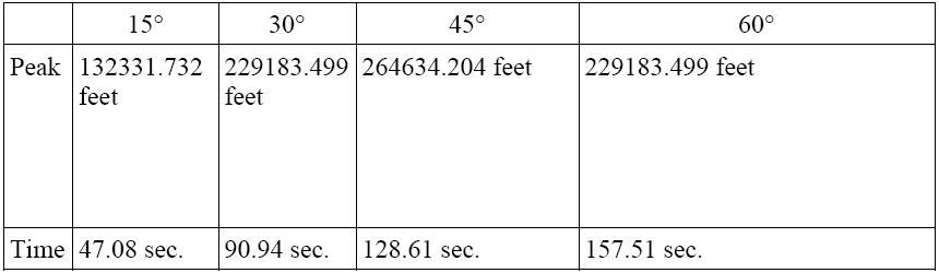
Data Without Air Risistance
Obviously, this lack of realism shows that air resistance is a major factor in bullet trajectory. Bullets do not
fly 2 minutes in the air; they fly in about 2 seconds.
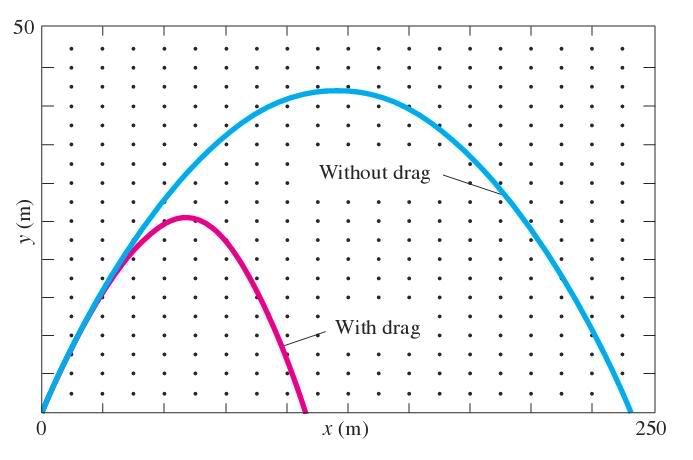
Graph Showing Air Resistance
Our Approach: We used JAVA as our computer program with Netbeans IDE. We first created a program t
hat did basic conversions. It could convert between centimeters and inches, grains to grams, MOA (minutes of an
angle) to radians, feet per second to miles per hour, and millibars to inches of mercury (air pressure). This wo
uld help us later when we had disorganized units because of different sources. Then, we created a program that c
alculated a bullet’s trajectory without air resistance. This used the equations mentioned above. |v| was determi
ned to be 2910 feet/sec. Since we used feet, 32 ft/sec²=gravity. The launch angle Θ was the input. Th
e program would then output the time it takes for the bullet to reach the ground, its maximum height and a graph
of its trajectory. Of course, this is opposite our program’s goal, but it’s easily modified so that distance is
an input and the angle was the output. The graph was especially challenging because of the difficulties scaling
the graph correctly as well as getting the computer to draw the graph. Also, since a computer can only connect l
ines and not actually draw a curve, we had to make the computer draw so many tiny lines that the human eye could
barely tell the difference between a curve and that many microscopic lines. This was done byincrementing t (time
) by .1 seconds. Then, we set up a program that does the same thing as the trajectory program, but it included a
ir resistance. In the drag equation, C and ρ are the variables (inputs). |v| is 2910 feet/sec=886.968m/s and
A=4.080637cm². Since drag is a force, and F=ma, we find acceleration by dividing F by m. m= 45.88961g. Howe
ver, it's more useful to find the acceleration in both the x and y directions. Ax=(-D/m)vvx. vx is the vector in
the x direction which equals cosΘv where Θ is the launch angle. Ay= -(g+D/mvvy). vy is the vector in
the x direction which equals sinΘv. g is gravity which is 9.8m/s². Once acceleration is determined, t
he concept of the time increment comes in. The acceleration is constantly changing, but for a small period of ti
me, it can be safely assumed to be constant. Our time increment is .01 seconds. In the equation without air resi
stance, gravity was the negative acceleration. Now, the acceleration is drag force so that's substituted into th
e equation instead. However, because these are increments, a change from a non-zero time increment to another no
n-zero time increment can happen. Therefore, the equations for x and y must be adjusted. Also, acceleration due
to drag isn't constant. However, over a short amount of time, it's constant enough. Vx+ΔVx= Vx+AxΔt
and Vy+ΔVy= Vy+AyΔt where Δt is our time increment .01. ΔVy or ΔVx is to be determ
ined by Ax=-Dv²cosΘ/m where v²=V²y+V²x and Ay= -(Dv²sinΘ/m+g). Then, the ax
and ay is put into the equation without air resistance where the gravity is substituted by acceleration. In para
meter form (in terms of t), x+Δx=x+vcosΘt+½Axt² andy+Δy=y+1.524+sinΘvt+&frac
12;Ayt². The 1.524 is added because snipers don't shoot on the ground. They're standing up so the gun's abo
ut 5 feet=1.524 meters off the ground on their hands. The computer outputs the graph and distance the bullet tra
vels when it touches the ground.
Our Most Significant Achievement: Our most significant achievement was gathering the information b
ecause compiling all the information from all the different sources was challenging. The information was split i
nto so many sources that it took the researcher many months to piece together the information. Often times, the
information was misleading, outdated, incorrect, or irrelevant. This is why the team had to scrutinize the resea
rch to ensure validity. This is also why the researcher had to constantly search for more information because ev
ery new program required new research and information that seemed correct needed fixing.
Sources and Helpful People:
|
|